Tubing / Bar Roller Designed and built by Ernie Leimkuhler 2/10/01
This whole project started with a desperate need to get some tubing curved for a commercial railing job. I had just finished a previous job where I needed long smooth curves in stainless steel hand rail tubing and the way I had achieved that was the way I have always had to. The tubing was racked against curved blocks of MDF on a table anchored to my driveway. This is a pain in the ass, and it is very easy to accidentally end up with a spiral. The bends must be gentle and close enough together to prevent noticeable kinks.
So when a commercial job came up that needed long shallow curves in a larger 2" tube, I decided to apply "the little grey cells" and finally build a roller to fit my needs.
The roller of my dreams is sold by Promaco and costs $4000. 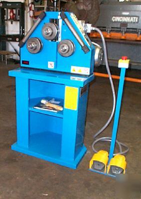
Promaco Roller
Unable to finance that beast I decided to build something good enough for my job.
Since the only milling machine I have access to is at school and it is a sorely abused machine with little tooling, I decided to figure out a solution that did not require the normal sliding racks that other tubing rollers use to adjust the relationship between the 2 stationary rolls and the 1 moving roll. This meant using a different system for tensioning the adjustable roller. I also considered that it is much easier to pull a screw than to push a screw. By pulling it I could reduce it's size.
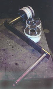
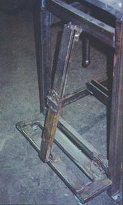
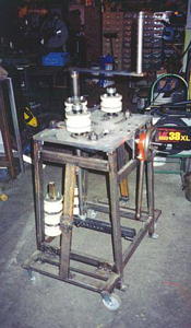
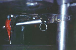
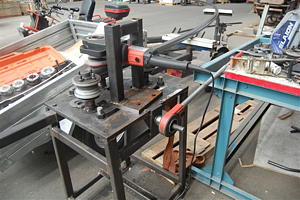
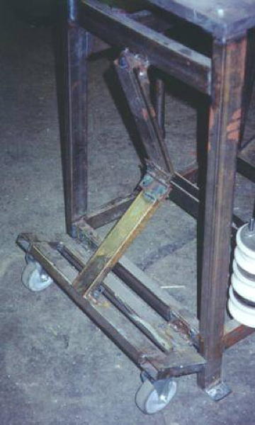
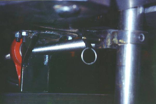
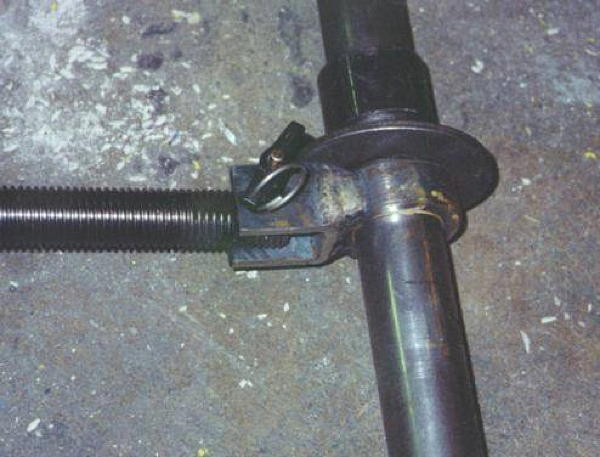
Hence my basic idea came to shape. Instead of using a sliding track, I would use a long bar, pivoted at the bottom by a ball-detent pin, and tensioned by a heavy screw. The crank handle idea came from years ago when I made a small bar coiling machine for 1/4" steel round bar.
I then hit upon the idea of making the distance between the stationary rollers adjustable by also using a swing arc idea. This way I could have them far apart for long gentle curves in heavy material and have them close together for tighter bends in lighter material. This also allowed me to make the top plate from 1" aluminum plate instead of steel. A great saving in weight and fabrication time.
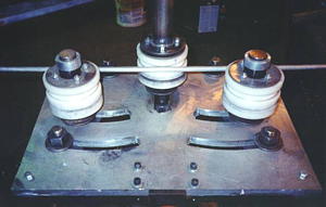
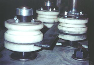
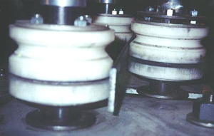
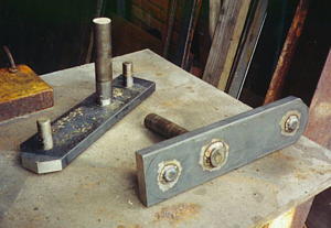
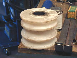
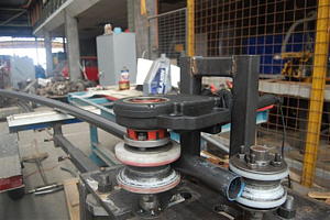
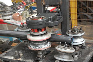
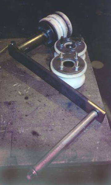
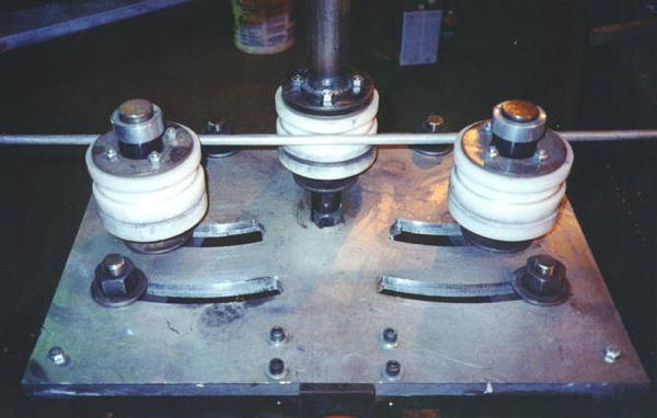
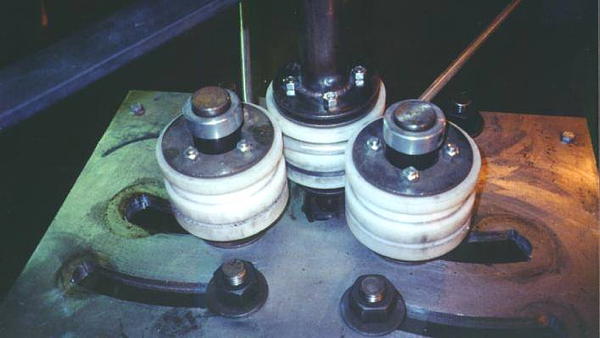
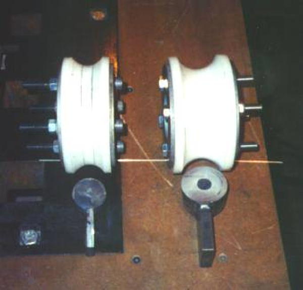
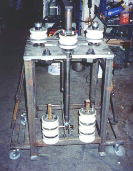
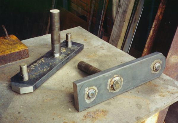
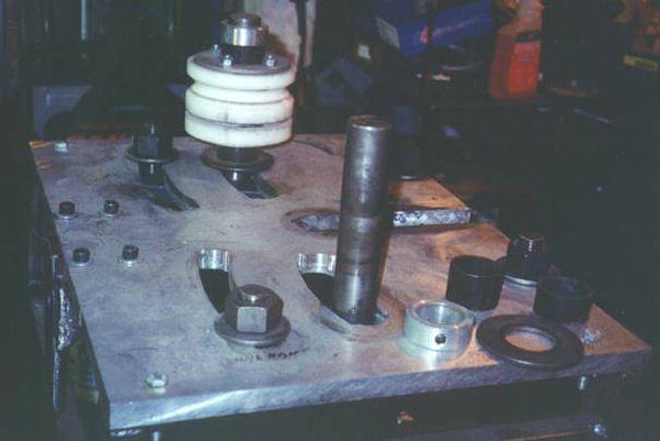
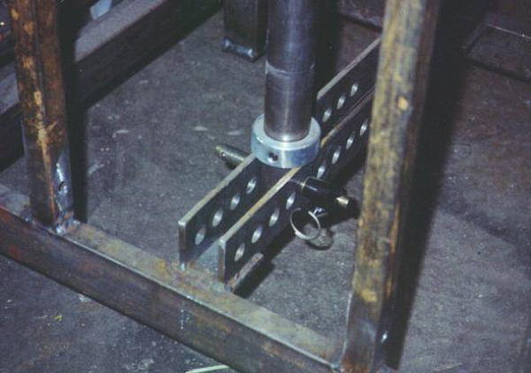
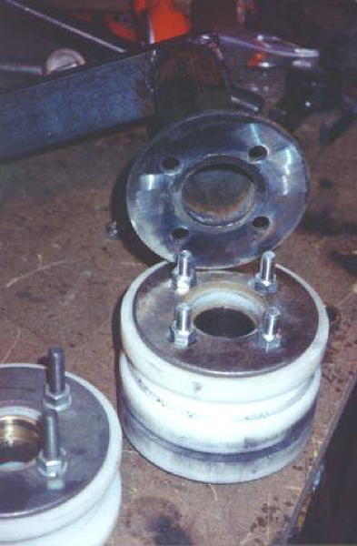
The material for the roller dies was always going to be a plastic, and I settled on Delrin for cost and machinability. 5" round bar Delrin is readily available in Seattle for about $90 per linear foot. Delrin is a breeze to machine, and comes off as long ribbons. To reduce friction I pressed oilite bronze bearings into the delrin blocks. The bearings I used where 1-1/2" ID x 1/8" wall x 2" long and 1" long. I just stacked them inside the block to make up the height of the die. I little tenacious oil helps keep them lubed. One problem with plastic dies is that they have a bad habit of spreading under load, so I needed stiffener plates for the top and bottom, held in place by grade 5, 3/8" through bolts. This also made mounting the crank handle pretty easy. I just used longer bolts for the center roll, and used another of the side plates as the base for the crank. It seemed silly to cut round plates from 1/4" steel when I can just buy them. The code phrase is 2" standard flat washer. They work perfectly, and cost about $1 each. I made up a drill guide for the side plates and the roller dies so all the holes would line up. The bolt holes are all drilled to 7/16" dia. to allow for the plastic's tendency to shift.
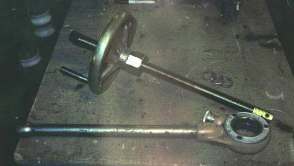
I used 1-1/2" cold rolled bar stock for all of the main shafts and a high tensile 1" x 8 tpi all thread rod called "B7" by Tacoma Screw. The stop collars are a stock item from any bearing supplier. My top plate was fabricated using a 1-1/2 HP Porter cable router and solid carbide 1/2" spiral flute end mills. I made a very strong swing arc guide for the router to cut all of the arced slots. Lots of ZEP Big Orange citrus cleaner as cutting fluid and it came out fine. If I was to make another I would likely have the top plate cut by a water jet shop or CNC Machine shop. The tension wheel was found at Boeing salvage, and was made by Destaco. I welded a 1" x 8 high strength nut to it and later added the speeder handle.
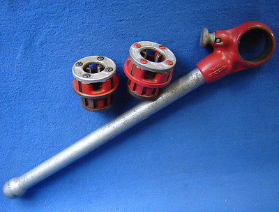
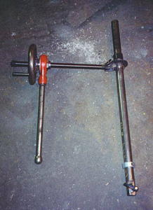
Rigid Ratchet
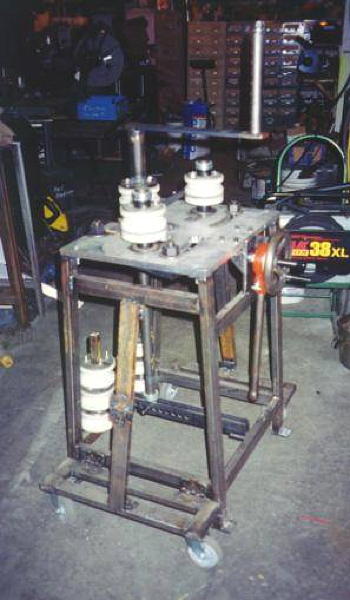
It wasn't until much later that I hit upon the idea of the Rigid Tools pipe threading ratchet. That one addition makes the whole tool immensely powerful. I can easily bend 1-1/2" pipe into a 6' ring using that ratchet, taking many passes through the dies. The wheel was built up with weld bead and ground off to the 2" Octagon to fit the ratchet. Obviously it would have been easier to machine the octagon and weld it on, but oh well.
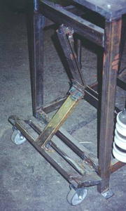
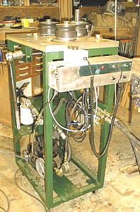
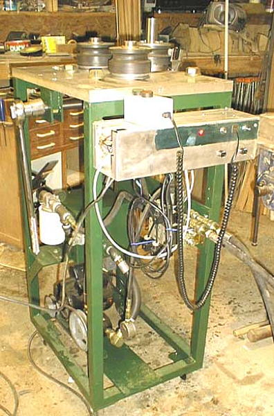
The frame of the roller is built with 1" x 2" x 0.065" wall steel tubing. Anything equally strong could be used. The broken arm wheel bases are a piece of theatre scenery hardware we used a lot at the Seattle Opera. They are an excellent solution for retractable wheels on light machinery.
To use the roller it must be rigidly mounted to something. I have concrete anchors in the floor of my shop and in the field I ratchet strap it to my truck bumper.
As the tubing passes back and forth through the roller you need either a pair of assistants to hold the ends up, or a bunch of adjustable roller stands.
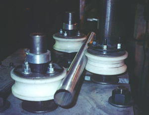
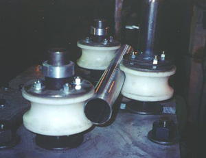
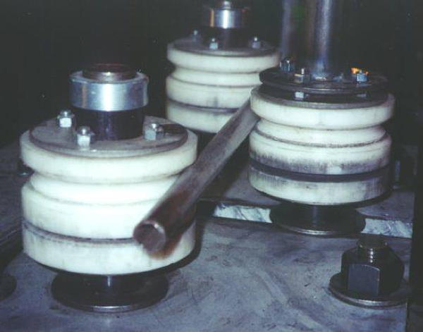
A few more points. The Delrin can easily be machined to custom shapes by simply making a cutter with the profile desired. For the 1-1/2" and 2" tubing rollers I made custom cutters from some handy pieces of steel.
Actually using the roller requires some practice. You can put a serious curve in the tube very quickly, but if you go too quickly you can stall the roller. It is also quite easy to un-roll a piece if you go too far. The lower pin-rack acts as the lower pivot point for the main bar. As the screw goes in and out it will swing back and forth however you don't want it to get too far from vertical or the dies will stop lining up nicely. So whenever the bar gets to leaning over far enough that you can switch the bottom pivot hole, do so. For shallow bends one pivot hole will usually suffice, picking that hole takes a little practice. The roller die that spins on the main bar is not anchored to anything except the Hand Crank. This allows the die to float up and down as needed by the angle of the bar. The material itself works to keep the dies aligned.
To achieve a desired curve it is best to draw the curve on the floor or a large table, so you can lay the piece on top as you progress closer to the desired curve.
The Rigid Tools pipe threading ratchet cost me $50 at a pawn shop. They show up regularly at flea markets and used tool stores.
You could use Grade 5 or Grade 8 bolts instead of the ball-detent pins. I use the pins because I have them. One nice thing about the pins is that for transport or storage the Wheel, Screw, and main bar and all be pulled easily with no tools.
To keep the dies at the proper height I used short pieces of 2" thin wall round tube as spacers.
To reduce friction on the Tension Wheel I use a flat cylindrical roller thrust bearing and to adjust for the varying angle of the screw I use a spherical washer set (both from Reid Tool). The combination of the 2 makes for a much smoother operation.
If anybody can figure out how to put a power drive on this machine, let me know.
Oh yeah, total cost was about $500
Now on to the drawings and pictures. I recommend finding something to read the CAD (.dxf) versions of the drawings. It makes them much more useful. The GIF versions are for those without any CAD program.
Roller — Side View (dxf, gif) shows the main structure of the machine and how the working parts relate to the frame.
Roller — Top View (dxf, gif) shows the top plate and the Swing Arms.
Roller — Parts A (dxf, gif) shows the main working parts and their names.
Roller — Parts B (dxf, gif) shows full drawings for components of the Tension Screw Mechanism.
Roller — Parts C (dxf, gif) shows full drawings of the dies and hand crank.
P.S. If anybody comes up with any improvements, please keep me informed.


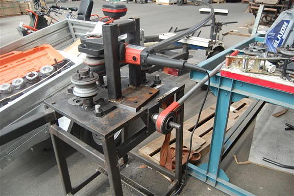
Bender drive
Bender roll

Bender roll
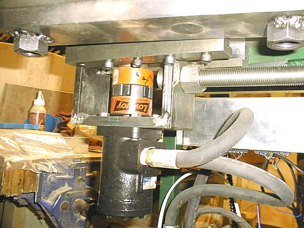
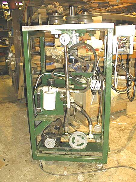
Power conversion
Power conversion
Power conversion

Top plate


Bender drive
Bender roll
Bender roll
Power conversion

Power conversion

Power conversion
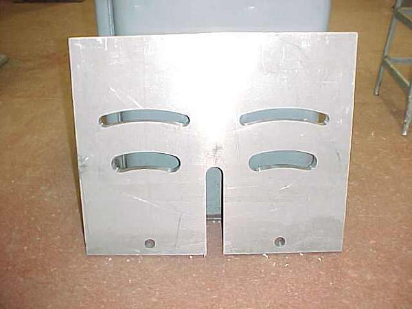
Top plate